Introduction
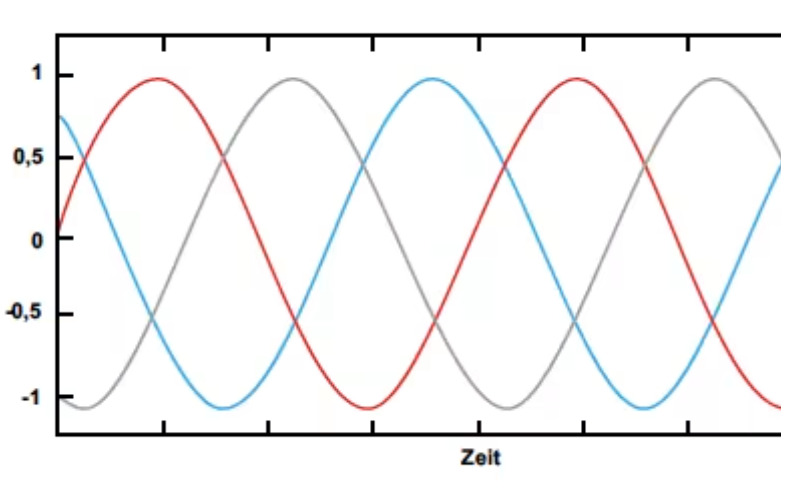
3-phase power is a method of alternating current (AC) generation, transmission, and distribution that uses three electrical conductors, each carrying AC voltage of the same frequency and amplitude but offset by 120 degrees—one-third of a 360-degree cycle as shown in Figure 1—to provide that power delivery is evenly distributed, balanced, and continuous.
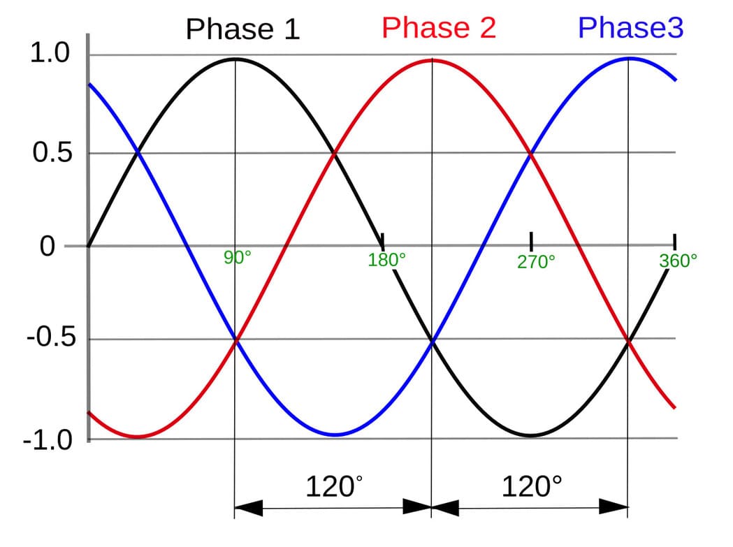
Figure 1 - 3 phase AC power waveform
The reliable and efficient power delivery makes 3-phase system the exclusive choice in today’s industrial and commercial applications where high currents, reliable power, and the ability to support heavy loads are vital.
Heavy electrical loads and sudden changes in load often cause transient overvoltages or surges, which can lead to significant damage to connected electrical facilities and equipment. In addition, the threat of direct lightning strikes renders 3-phase systems vulnerable to power spikes—making surge protection for three phase systems an indispensable measure for maintaining system security and reliability.
This blog explores the importance of surge protection in 3-phase systems, aiming to help readers understand its role in electrical safety and make informed decisions when selecting and applying the right SPDs.
What is 3-phase surge protection and what is a 3-phase SPD?
3-phase surge protection refers to the use of specially designed surge protection devices (SPDs) to protect 3-phase power systems from transient overvoltages. These overvoltages, or surges, can result from internal sources such as capacitor switching, motor starting/stopping, or load shedding, as well as external sources like lightning strikes or grid switching events.
Surge protection device working principle
Surge protective devices work by rapidly diverting excess energy away from protected circuits once the voltage exceeds a defined threshold. To achieve this, they employ components such as metal oxide varistors (MOVs), gas discharge tubes (GDTs), depending on the response speed and energy-handling capability required.
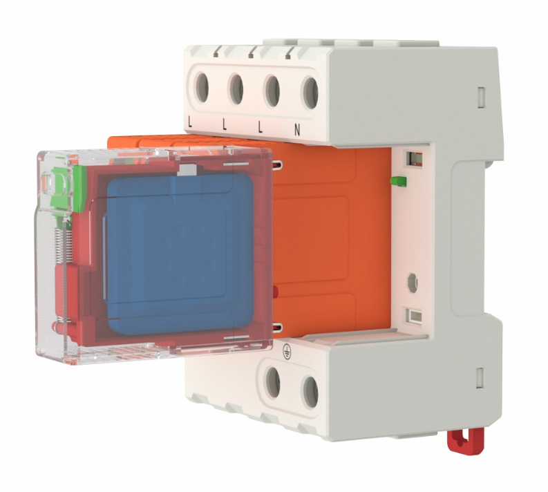
Figure 2 - Metal oxide varistor inside the SPD module
Modes of protection in 3-phase surge protection
In a 3-phase system, which typically consists of three live conductors (L1, L2, L3) and a neutral, surges can travel through various combinations of the lines—such as line-to-line, line-to-neutral, or line-to-ground. This makes three phase surge protection more complex compared to single phase systems. To provide comprehensive protection, a 3-phase SPD is designed to cover multiple modes of protection, often including:
Phase-to-Phase (L1–L2, L2–L3, L3–L1)
This mode protects against surges occurring between any two of the live conductors. For instance, a voltage spike between L1 and L2 in three phase systems can be diverted by the SPD, preventing damage to equipment connected across those phases. This is particularly important for phase-to-phase loads, such as three-phase motors or variable frequency drives (VFDs).
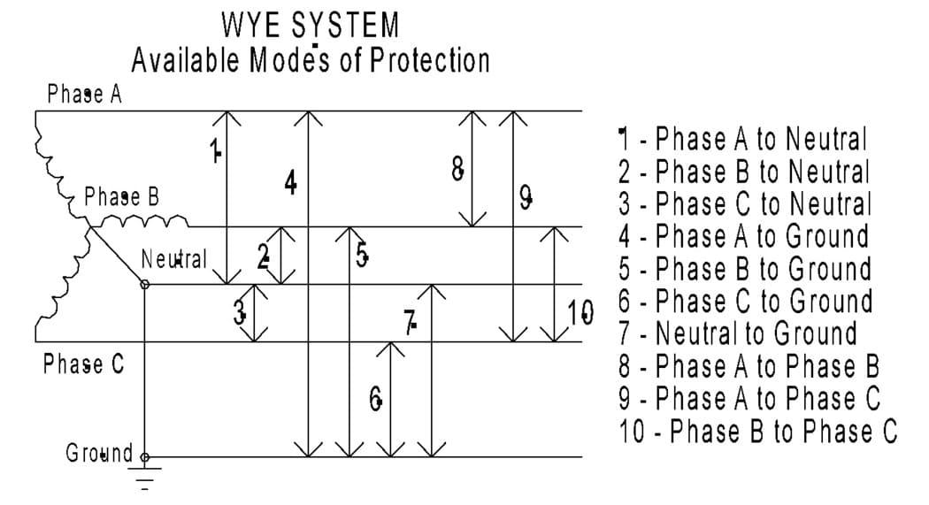
Figure 3 - Modes of surge protection
Phase-to-Neutral (L–N)
In this mode, the SPD shields the circuit from surges between any live conductor (L1, L2, or L3) and the neutral point. Downstream devices rely on the neutral as their return path, so protecting L–N is critical for preventing common-mode surges that could damage single-phase loads (e.g., lighting or control circuits) connected to one phase of the 3-phase system.
Phase/Neutral-to-Protective Earth (L/N–PE)
This mode protects against surges that may travel from either a live conductor or the neutral line to earth ground. It addresses differential-mode spikes traveling along the conductors and common-mode surges induced by external factors (e.g., lightning coupling into the grounding system).
Why 3-phase surge protection is critical
In modern electrical systems, especially in industrial and commercial environments, 3-phase power distribution is the norm due to its efficiency in delivering large amounts of electricity. However, with the widespread use of sensitive electronic equipment and automation systems, the three phase system has become increasingly vulnerable to surges—sudden spikes in voltage caused by lightning strikes, switching operations, or equipment faults.
1.Protecting Sensitive and Expensive Equipment
One of the main reasons for installing 3-phase surge protection is to protect expensive and sensitive equipment such as programmable logic controllers (PLCs), variable frequency drives (VFDs), and other microprocessor-based devices that are integral to industrial automation and manufacturing processes, and even a brief voltage spike can result in malfunction or irreversible damage. For instance, a lightning-induced surge that travels through an unprotected power line into a factory's control system can instantly disable the control panels, halt production, and cause financial losses running into millions of dollars.
2.Preventing Phase Imbalance and Equipment Stress
Another key reason is the prevention of unbalanced phase conditions. A surge affecting only one or two phases in a 3-phase system can create an imbalance, leading to overheating in motors, false tripping of protection devices, and reduced efficiency. In more severe cases, it may cause motors to run in reverse or stall entirely. A real-world example is a commercial HVAC system powered by a 3-phase motor: if one phase is hit by a transient overvoltage and the others are not, the motor may overheat or fail prematurely.
3.Reducing Maintenance Costs and Extending Equipment Life
Finally, from a long-term perspective, 3-phase surge protection helps extend the lifespan of electrical systems. Frequent small surges—often unnoticed—gradually degrade insulation, circuit boards, and semiconductor components. Over time, this leads to more frequent maintenance, unexpected equipment failures, and higher operational costs. By installing SPDs that cover all three phases and the neutral-to-ground paths, facility managers can proactively manage surge risks and improve the reliability and longevity of their assets.
 |
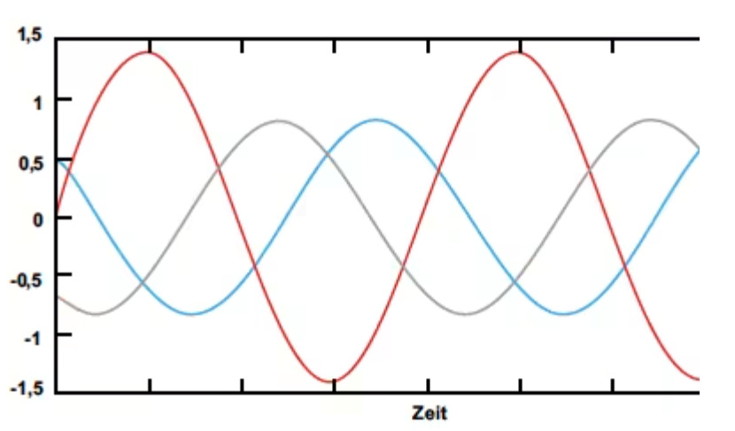 |
Figure 4 - phase balance and imbalance in 3-phase systems
How to select the right SPD for 3-phase surge protection
In practice, 3-phase SPDs are strategically installed at the main distribution board, subpanels, and critical equipment interfaces. They are a key component of a layered surge protection strategy and must be selected based on system voltage, earthing type (e.g., TN, TT, IT), and the expected surge exposure level (e.g., urban, industrial, or lightning-prone environments).
1.3-phase SPD types
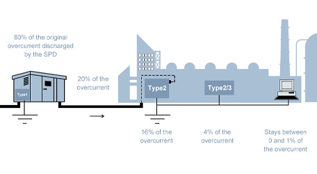
In a 3-phase electrical system, surge protection is implemented through a cascading strategy involving SPDs of different types and pole configurations, depending on the system layout and the criticality of the equipment.
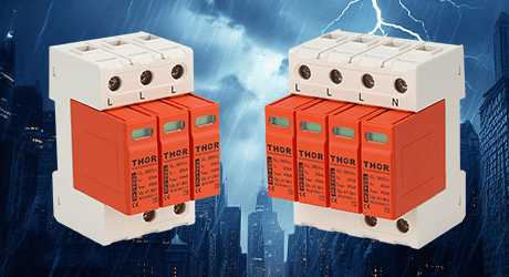
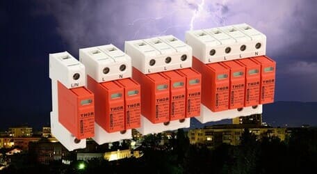
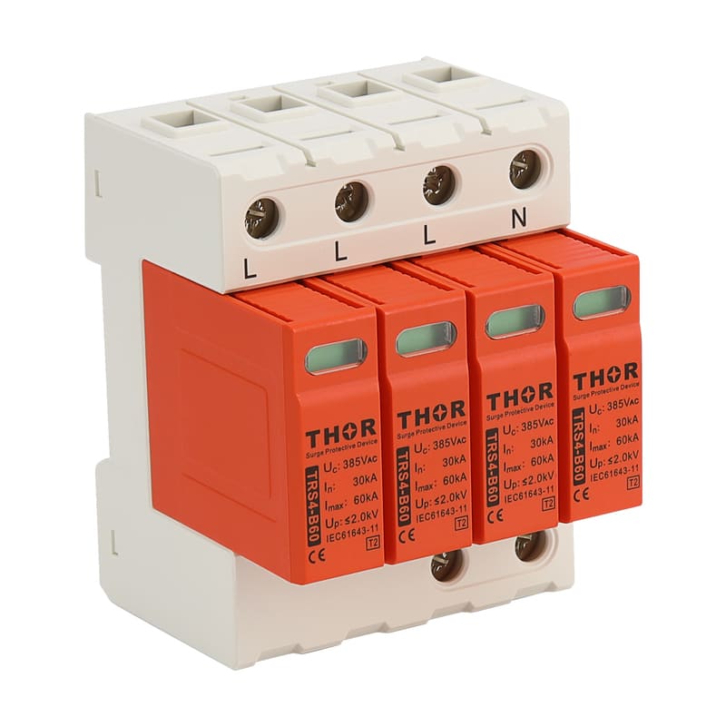
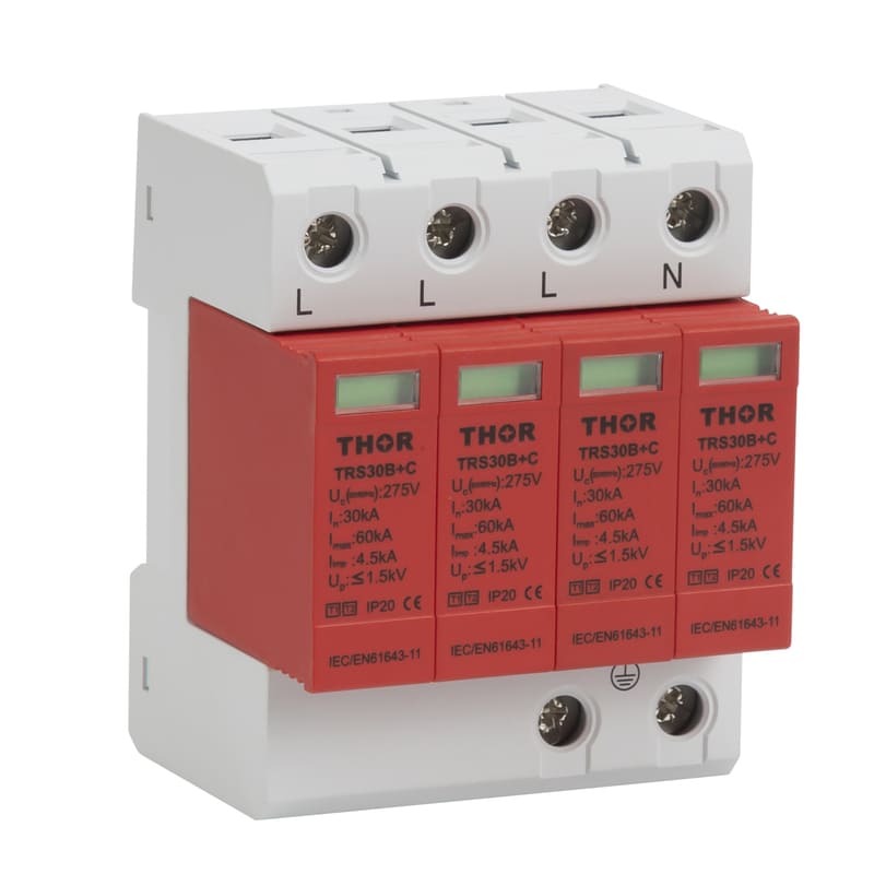
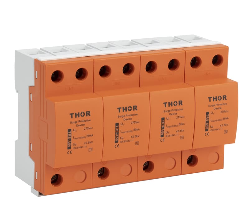
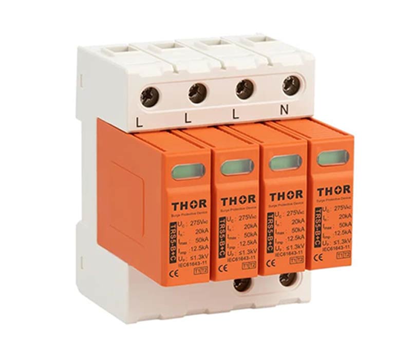
Type 1 SPDs with high nominal discharge current capability, such as the TRS-A50 rated at 50 kA, and combined Type 1+2 SPDs like the TRS5, are typically installed at the main distribution panel—also known as the service entrance—to suppress the majority of incoming overvoltages in a three-phase system. They are essential in buildings with external lightning protection systems or where the installation is exposed to high lightning risk.
 |
|
| Type 1 TRS-A50 surge protection device for three phase system | TRS5 type 1+2 surge arrester, 3+1 configuration for 3 phase system |
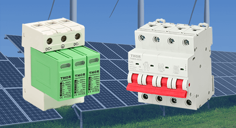
Further downstream, Type 2 SPDs, for example, TRS-B80, which boasts a high In rating of 40 kA are commonly deployed in sub-distribution panels to suppress residual surges that Type 1 devices may not fully eliminate.
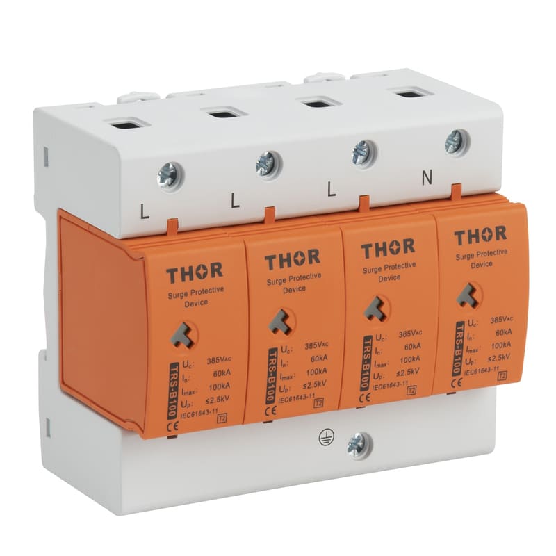
Type 2 TRS-B80 three phase surge suppressor, 3+1 configuration
Both Type 1 and Type 2 SPDs for 3-phase systems usually come in 3- or 4-pole versions, selected based on whether a neutral conductor is present in the system.
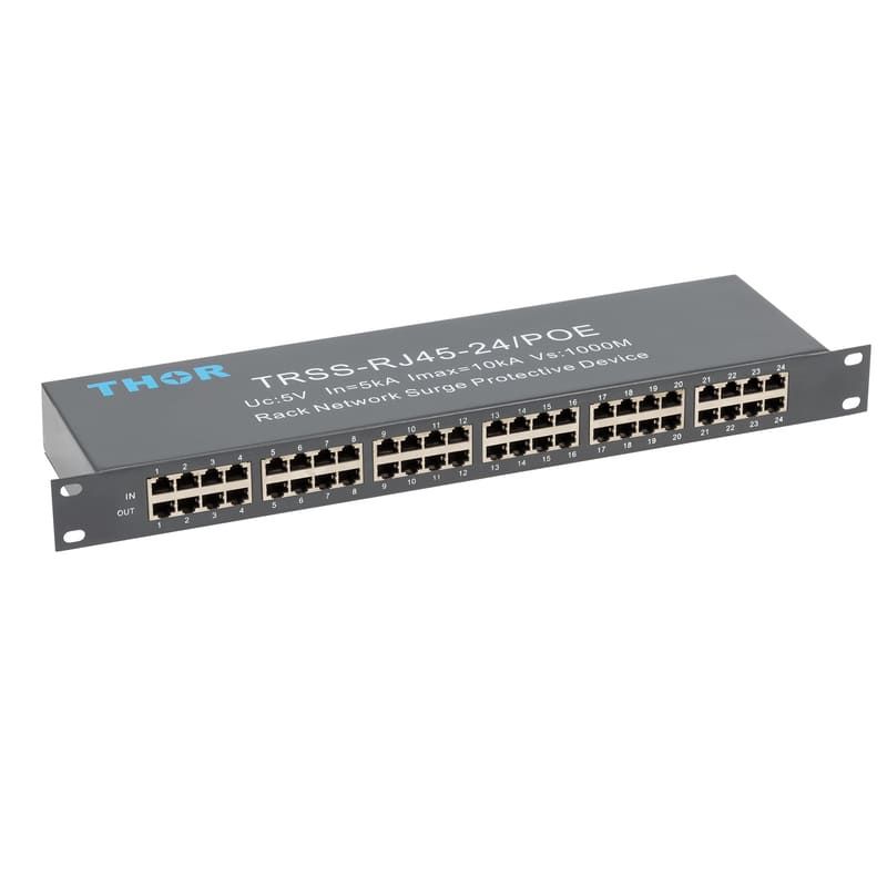
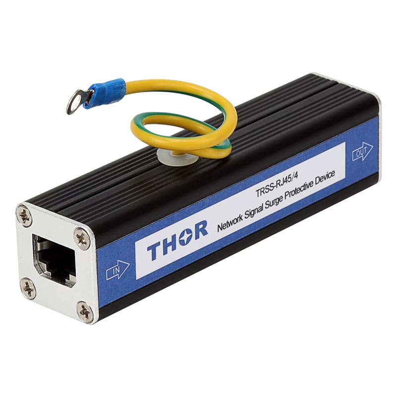
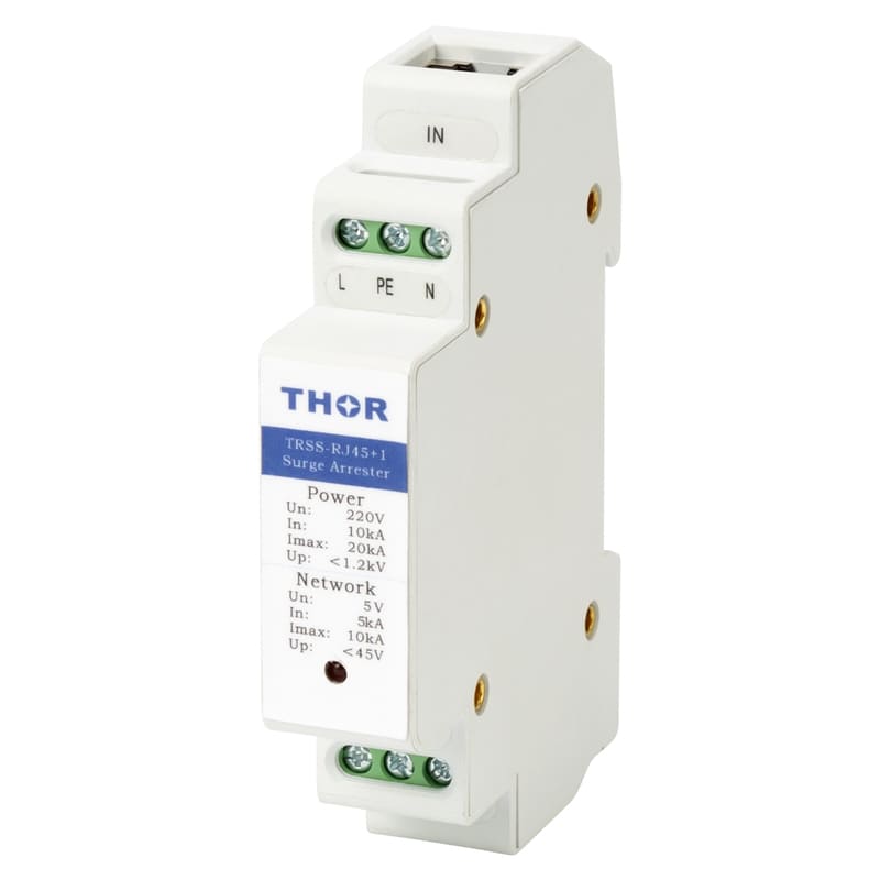
At the point of use, Type 3 SPDs TRSS series are used to protect sensitive devices such as computers, servers, medical instruments, and meters. Type 3 SPDs are typically connected to a single-phase supply (either Line-to-Neutral or Line-to-Earth), and they provide fine-level protection with low clamping voltages. But it must be properly coordinated with upstream three phase Type 1 and Type 2 SPDs to guarantee they are not overwhelmed by high-energy surges.
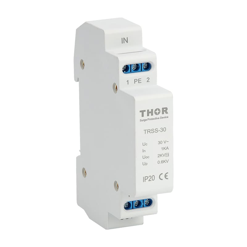
Type 3 TRSS series AC SPD
2.Key technical ratings to consider
The ratings of a three-phase SPD are critical factors to consider before making a selection or purchase, as the configuration of three-phase systems can vary depending on the specific setup. Higher ratings do not necessarily guarantee better protection—what matters most is choosing specifications that are properly matched to the characteristics and requirements of the system you intend to protect.
One of the most important factors is the maximum continuous operating voltage (Uc), which indicates the highest voltage the SPD can withstand without degradation over time. For three-phase systems, it's critical to choose three phase SPDs with a Uc rating that matches or slightly exceeds the system's nominal voltage for better protection.
Another vital consideration is the nominal discharge current (In) and maximum discharge current (Imax), which define the amount of surge current the SPD can safely handle during transient events like lightning strikes or switching operations. A higher In and Imax rating typically means the SPD is better equipped to protect against larger surges. However, it's important to balance ratings with the actual surge risk in your environment to avoid over-specifying and increasing costs unnecessarily.
The voltage protection level (Up), or clamping voltage, indicates the maximum voltage the SPD allows through to the protected system during a surge event. For optimal protection, the lower the Up, the better, as it limits the voltage exposure to sensitive equipment. However, a lower Up typically correlates with a faster response time, so it’s essential to ensure that the SPD can handle the surges effectively while keeping the equipment safe.
Finally, when selecting a three-phase suppressor, you must consider the number of poles—either 3-pole or 4-pole, depending on whether a neutral conductor is present in your system.
Make sure 3-phase SPD you choose are certified to meet internationally recognized standards, such as IEC and TÜV standards.
3.Match SPDs to your earthing/grounding system.
The selection of three phase surge protection device depends heavily on the type of earthing system as grounding methods directly affect SPD structure and coordination with surge protective devices, especially when it comes to three phase protection.
In TN systems, where the neutral and protective earth are interconnected, SPDs must be carefully selected to avoid interference with residual current devices (RCDs). If an SPD uses MOVs between N and PE, small leakage currents can occur under normal operation, which may cause nuisance tripping of RCDs—especially since the potential difference between N and PE is very low in TN systems.
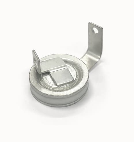
Figure 5 - Gas discharge tube
To address this, many SPDs in TN systems use gas discharge tubes (GDTs) or spark gaps between N and PE. GDTs remain open under normal conditions and only conduct during surge events, effectively eliminating leakage currents and minimizing the risk of false tripping.
In contrast, TT systems require a different approach. Since the neutral and earth are not directly connected, a Type A or Type B RCD is typically required to detect leakage currents and maintain electrical safety. In this setup, it's important that the SPD does not bypass the RCD or introduce a permanent leakage path that could reduce RCD sensitivity.
Unlike TN or TT systems, where the neutral is solidly earthed, an IT system maintains the neutral at a floating potential. When selecting SPDs for IT systems in three phase setups, several factors must be taken into account.
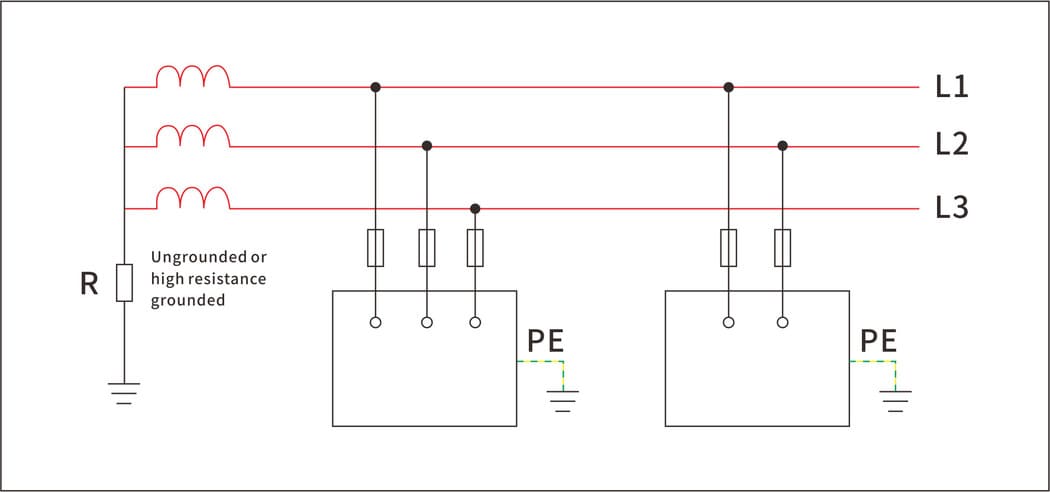
Figure 6 - Three phase IT earthing system with an ungrounded or high-resistance grounded neutral at the service entrance.
First, because the neutral is not referenced to earth, traditional L-N or N-PE protection modes are often inappropriate or unnecessary. Instead, protection is usually provided between L-L (line-to-line) and L-PE (line-to-earth), depending on the system configuration and the presence of grounding at the equipment level.
Moreover, many IT systems use insulation monitoring devices (IMDs) to detect the first insulation fault. SPDs installed in such systems must not interfere with the operation of these devices. Therefore, three phase surge protection devices with low or no continuous leakage current to earth are recommended—gas discharge tubes (GDTs) or specially designed low-leakage SPDs are often preferred over standard MOV-based devices.
Additionally, the risk of overvoltage between phases in an IT system can be higher due to the lack of a solid earth reference, which makes L-L surge protection essential, especially in cases in which equipment is sensitive to transient overvoltages across phases.
3-phase surge protection device wiring and installation
1.Wiring the SPD
● Connect each of the three phases (L1, L2, L3) to the SPD's input terminals as indicated by the manufacturer's wiring diagram.
● Connect the neutral (N) and earth (PE) terminals of the three phase surge arresters to the corresponding neutral and ground conductors in the system.
● Follow the exact wiring configuration suggested by the manufacturer to helps the SPD perform as intended and offer adequate protection.
If required by specific three phase system design, install the appropriate circuit protection devices, such as fuses or circuit breakers, in series with the SPD to prevent devices from faults or overload conditions.
2.Grounding
● make sure that the SPD is grounded to a low-resistance earth connection, typically less than 10 ohms, to ensure proper surge dissipation and safety.
● The PE (Protective Earth) terminal of the SPD should be securely connected to the grounding bar or ground conductor.
● A poor or improperly installed ground can reduce the SPD’s effectiveness.
3.Circuit Breakers or Fuses
● Install circuit breakers or fuses to protect the SPD from overcurrent conditions. They help prevent damage to SPDs during surge events or faults by interrupting the power supply when a fault occurs.
● The circuit protection devices should be rated according to the SPD’s maximum discharge capacity so that they can handle expected surge currents without tripping unnecessarily.
4.Mount the 3-Phase Surge Protection Device
● Install the SPD as close as possible to the main distribution board or incoming supply to minimize the lead length between the SPD and the protected equipment.
● Keeping lead lengths short (less than 0.5 meters if possible) contributes to faster response time to voltage surges and enhances the SPD's protection effectiveness.
● Proper installation near the main supply also helps to protect downstream equipment and prevent unnecessary voltage spikes from reaching sensitive devices.
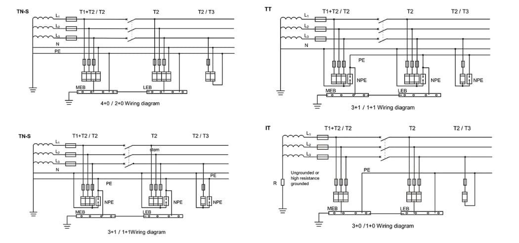
Figure 7 - 3-phase surge device wiring diagram for 3 types of earthing/grounding systems
5.Clearance and Creepage Distance
● Maintain appropriate clearance and creepage distances between the SPD’s terminals and surrounding conductive parts, in accordance with the three phase system's voltage level and applicable standards (such as IEC or UL).
● Proper spacing reduces the risk of electrical arcing or short-circuiting between live parts
● Refer to the manufacturer’s guidelines for the recommended distances to meet safety and regulatory requirements.