Introduction
A well-designed grounding system—also referred to as an earthing system—is fundamental to the safety, performance, and reliability of any electrical installation. It provides a low-impedance path for fault currents, stabilizes voltage, and minimizes the risk of electric shock or fire. Depending on the application, infrastructure, and regulatory requirements, different earthing configurations such as TN, TT, and IT are employed.
Equipotential bonding works alongside grounding to further enhance electrical safety. It minimizes voltage differences across exposed conductive parts, especially under fault conditions, helping protect both people and equipment. This article outlines the key grounding system types, their core components, and how equipotential bonding supports system integrity.
Grounding systems in electrical installations
In any electrical system, grounding provides a deliberate, low-resistance pathway for fault currents to flow safely into the earth. This function ensures that abnormal voltages resulting from insulation failure or accidental contact are quickly cleared by protective devices.
The grounding system typically connects metallic enclosures, frames, exposed conductive parts, and other non-current-carrying components to ground through a network of conductors and electrodes. Beyond fault clearance, grounding stabilizes system voltage by managing overvoltages caused by lightning or switching transients.
Terminology varies slightly by region. “Grounding” is used in North American standards such as the NEC, while “earthing” appears in IEC documentation. Despite linguistic differences, both terms refer to the same safety-critical concept: the safe dissipation of fault energy.
In installations using three-phase or distributed systems, careful coordination between ground and neutral conductors is essential. Improper segregation or bonding of these paths can compromise safety. Equipotential bonding complements this coordination by eliminating voltage gradients between accessible conductive surfaces.
Overview of earthing system types: TN, TT, and IT
Modern power distribution relies on specific earthing system configurations tailored to site-specific demands and codes. The three primary types—TN, TT, and IT—differ in how the source, protective devices, and exposed conductive parts are interconnected and grounded.
TN System (Terra Neutral)
In a TN system, the power supply’s neutral point is directly connected to earth. Exposed conductive parts in the installation are also connected to this earth via a protective conductor. TN systems are subdivided into three variants based on how the protective and neutral conductors are arranged:
TN-S: The protective earth (PE) and neutral (N) conductors remain separate throughout the installation.

Figure 1 - TN-S earthing system diagram
TN-C: A single conductor (PEN) serves both protective and neutral functions.

Figure 2 - TN-C earthing system diagram
TN-C-S: The PEN conductor is used for part of the system, then split into separate PE and N conductors closer to the installation.

Figure 3 - TN-C-S earthing system diagram
TN systems are commonly used in commercial and industrial environments due to their robust protection and relatively low earth fault loop impedance.
TT System
The TT configuration connects the installation’s exposed conductive parts to a local earth electrode, independent of the utility's grounding system. In TT systems, fault current paths typically involve higher loop impedance, requiring residual current devices (RCDs) for reliable disconnection. These systems are often used in rural areas or installations where utility grounding is unreliable or inaccessible.

Figure 4 - TT earthing system diagram
IT System

Figure 5 - IT earthing system diagram
An IT system has its power supply either isolated from earth or connected through a high impedance. Exposed conductive parts are grounded locally. IT systems are especially valuable in settings where uninterrupted power is essential, such as hospitals, laboratories, and industrial plants. The first insulation fault in an IT system does not necessarily trigger disconnection, which allows time for maintenance without loss of service.
System selection depends on factors such as soil resistivity, regulatory requirements, power supply characteristics, and the expected fault-clearing time. Each system type has distinct implementation criteria and safety considerations.
Grounding methods and components
The effectiveness of a grounding system depends not only on its configuration but also on the methods and materials used for implementation. The core objective remains to provide a reliable path for fault current to reach the earth.
Grounding electrodes form the physical link between the system and the ground. Common types include:
Ground rods: Vertically driven into the soil, typically made of copper-bonded steel.

Ground plates: Buried horizontally in the soil, offering more surface area in limited-depth situations.

Grounding strips: Long horizontal conductors, often used in soil with high resistivity.

Grounding pipes: Hollow steel pipes driven into the earth for deeper penetration.

Material selection—often copper or galvanized steel—depends on corrosion resistance, conductivity, and soil characteristics.
In large installations such as substations or data centers, grid earthing or ground rings are common. These involve interconnecting multiple buried conductors, creating a broad surface area to lower ground resistance. Grid systems are particularly effective in handling high fault currents and ensuring consistent potential distribution.
The ground busbar (or grounding bar) provides a central point of termination for multiple grounding conductors. Typically installed inside distribution panels, control cabinets, or equipment rooms, it simplifies maintenance and testing.

Another widely used method involves concrete-encased electrodes, also known as Ufer grounds. These leverage the conductive properties of concrete by embedding a steel conductor or rebar in the foundation structure. They offer stable performance in areas with poor soil conductivity.
All components must be properly sized and securely bonded to ensure low impedance. Failure in any part of the system compromises overall safety.

Equipotential bonding in electrical systems
Equipotential bonding enhances electrical safety by interconnecting all exposed and extraneous conductive parts, such as structural steel, metal pipes, and cable trays. The objective is to maintain a common electrical potential across these components, thereby eliminating voltage differences that can arise during faults.

Figure 6 - Equipotential bonding system diagram
The bonding network is established using conductors that terminate at a central equipotential bonding busbar. This centralized approach allows for clear organization, simplified inspections, and easier compliance with regulations. Diagrams help document the bonding layout and ensure proper connections are maintained over time.
Equipotential bonding can be divided into two main categories:
Protective bonding: Required in all installations to connect exposed metalwork that could introduce external voltages into the system.
Supplementary bonding: Used in areas with increased risk of electric shock, such as bathrooms, medical facilities, and swimming pools. It reinforces safety by connecting additional conductive parts that might not be included in the main bonding network.
An incomplete or poorly executed bonding scheme can leave installations vulnerable, even if the grounding system itself is well designed. Reliable bonding depends on proper conductor sizing, secure terminations, and careful attention to regulatory requirements.
Design and implementation guidelines
The process of designing a grounding system starts with a thorough assessment of site conditions, particularly soil resistivity. This value directly influences electrode selection, conductor sizing, and grounding topology.
Once the system type is selected (TN, TT, or IT), implementation must follow a methodical approach. This includes:
● Installing properly rated electrodes (e.g., rods, grids, or Ufer grounds).
● Using corrosion-resistant, low-impedance conductors.
● Keeping conductor paths as short and direct as possible.
● Ensuring all connections are mechanically strong and electrically reliable.
In complex environments such as industrial plants or high-voltage switchyards, additional configurations should be considered, including reactance grounding, resistance grounding, and high-resistance grounding—each suited to specific operational and protection requirements.
Earthing system diagrams are crucial in practical earthing project as it regulates conductor routing, connection points, and grounding zones, which helps maintain consistency during maintenance and compliance checks.
Pitfalls in grounding and bonding systems
Despite their critical role, grounding and bonding systems are often undermined by avoidable errors.
A few common issues include:
● Undersized conductors: Lead to excessive impedance, delaying protective device response.
● Loose or corroded connections: Can interrupt the grounding path entirely.
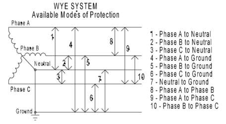
● Confusion between ground and neutral: Especially in delta systems, misidentification can cause dangerous conditions.
● Improper separation of system and equipment earthing: Blurs protection zones and allows fault energy to propagate unpredictably.
In bonding systems, omissions or inadequate conductor sizing reduce effectiveness. Misinterpreting terms like TN-C or incorrectly applying supplementary bonding introduces risks. Secure, clearly documented connections are essential for long-term safety.
Standards, testing, and maintenance
Grounding and bonding systems must conform to international and national standards. The IEC 60364 series outlines best practices for low-voltage installations. Local codes supplement these with country-specific guidance on conductor types, system selection, and safety clearances.
Technical resources, often distributed as downloadable guides or earthing PDFs, offer detailed insights into acceptable materials, testing procedures, and system design. Specialized configurations—such as those involving neutral grounding resistors or high-resistance grounding—require custom testing methods and advanced design knowledge.
Testing includes:
Earth resistance measurements using fall-of-potential or clamp methods.
Continuity verification for conductors and connections.
Visual inspection of bonding terminals for corrosion or mechanical damage.
Regular inspections and re-tests should be scheduled and documented. Keeping detailed records ensures ongoing compliance and facilitates corrective action when necessary.